SKU: OT6682 Varenummer: XR791 EAN: 8720828223468

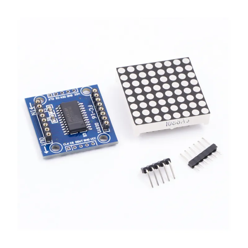
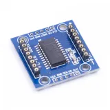
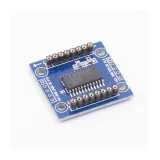
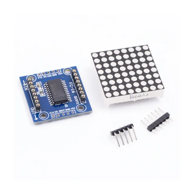
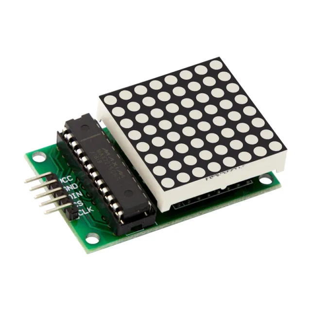
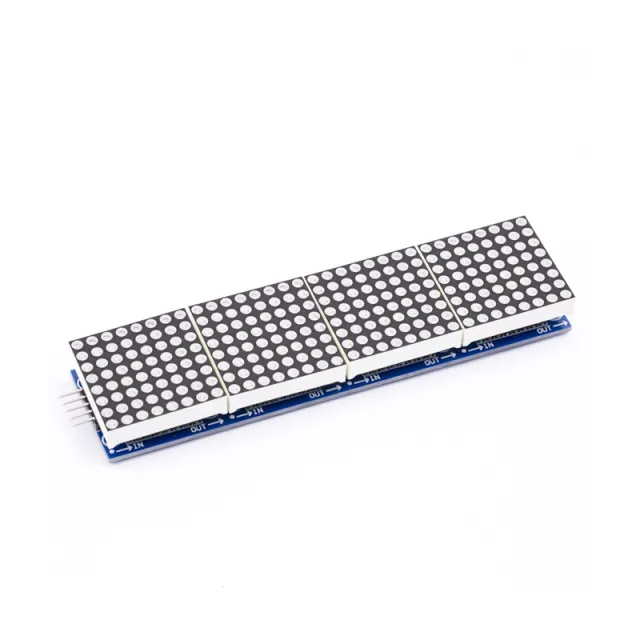
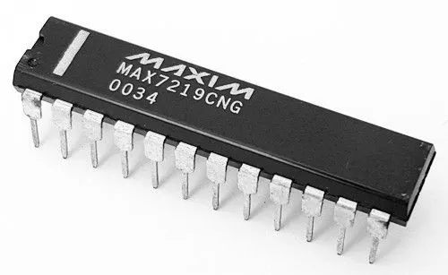
MAX7219 er en IC, der bruges til styring af LED-paneler med fælles katode, 7-segment displays og niveauindikatorer, som kommunikerer via SPI-interfacet. Dette board har et 8x8 dot matrix LED-display. Flere moduler kan kaskadekobles ved hjælp af header-forbindelser.
Specifikationer:
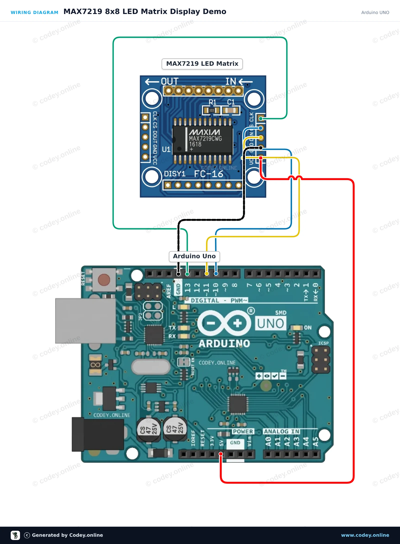
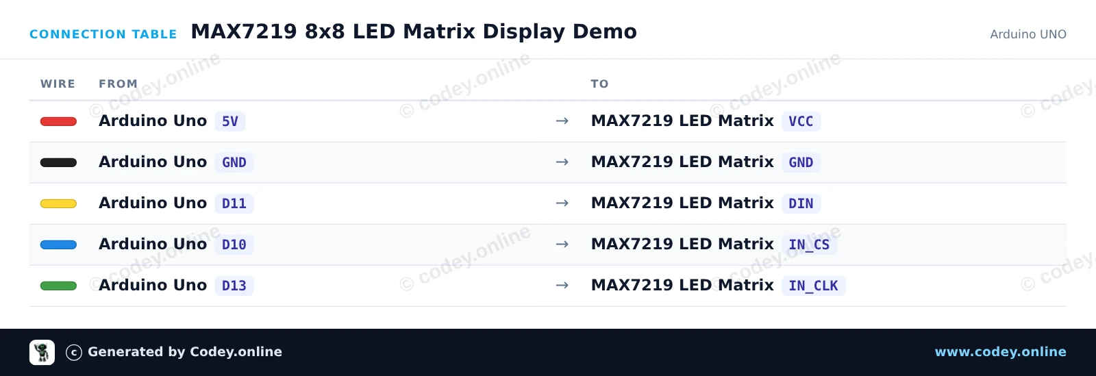
Sådan tilslutter du LED Matrix Module MAX7219 Grøn til en Arduino UNO eller ESP32, med en eksempelsketch, du kan uploade med det samme.
Dette projekt viser, hvordan man styrer en 8x8 MAX7219 LED-matrix med en Arduino Uno. Sketchen initialiserer displayet og skifter mellem at vise et hjerte, en smiley og en animation af et kvadrat, der vokser.
/*
 * ==================================================================
 *  Generated by Codey.online  —  https://www.codey.online
 * ==================================================================
 *  Project   : MAX7219 8x8 LED Matrix Display Demo
 *  Board     : Arduino UNO (arduino:avr:uno)
 *  Parts     : LED Matrix Module MAX7219
 *  Libraries : LedControl 1.0.6
 *
 *  Codey Online is an AI-powered browser IDE for Arduino and ESP32.
 *  Describe your project and Codey writes the code, draws the wiring
 *  diagram and uploads it to your board, straight from the browser.
 *  This code is free to use, modify and share, without warranty.
 * ==================================================================
 */

#include <LedControl.h>

const int DIN_PIN = 11;
const int CS_PIN  = 10;
const int CLK_PIN = 13;

LedControl lc = LedControl(DIN_PIN, CLK_PIN, CS_PIN, 1);

const byte HEART[8] = {
  B00000000,
  B01100110,
  B11111111,
  B11111111,
  B11111111,
  B01111110,
  B00111100,
  B00011000
};

const byte SMILE[8] = {
  B00111100,
  B01000010,
  B10100101,
  B10000001,
  B10100101,
  B10011001,
  B01000010,
  B00111100
};

void displayPattern(const byte pattern[8]) {
  for (int row = 0; row < 8; row++) {
    lc.setRow(0, row, pattern[row]);
  }
}

void setup() {
  Serial.begin(115200);
  Serial.println(F("MAX7219 LED Matrix Demo"));

  lc.shutdown(0, false);  // Wake up display
  lc.setIntensity(0, 8);   // Set brightness (0-15)
  lc.clearDisplay(0);
}

void loop() {
  // Show Heart
  displayPattern(HEART);
  delay(1500);

  // Show Smile
  displayPattern(SMILE);
  delay(1500);

  // Dot scan animation
  lc.clearDisplay(0);
  for (int row = 0; row < 8; row++) {
    for (int col = 0; col < 8; col++) {
      lc.setLed(0, row, col, true);
      delay(20);
    }
  }
  delay(500);
  lc.clearDisplay(0);
  delay(300);
}Nødvendige biblioteker: LedControl 1.0.6
Wiring diagram and example code generated by Codey.online — https://www.codey.online
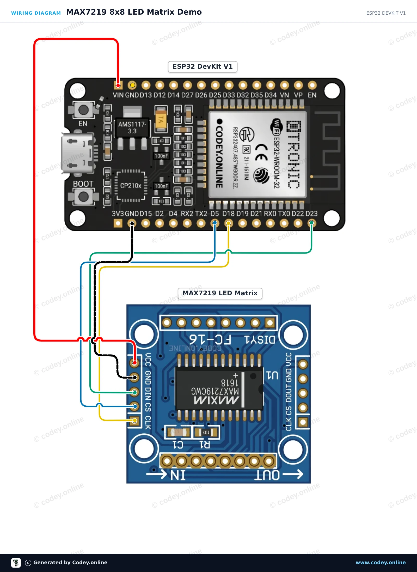
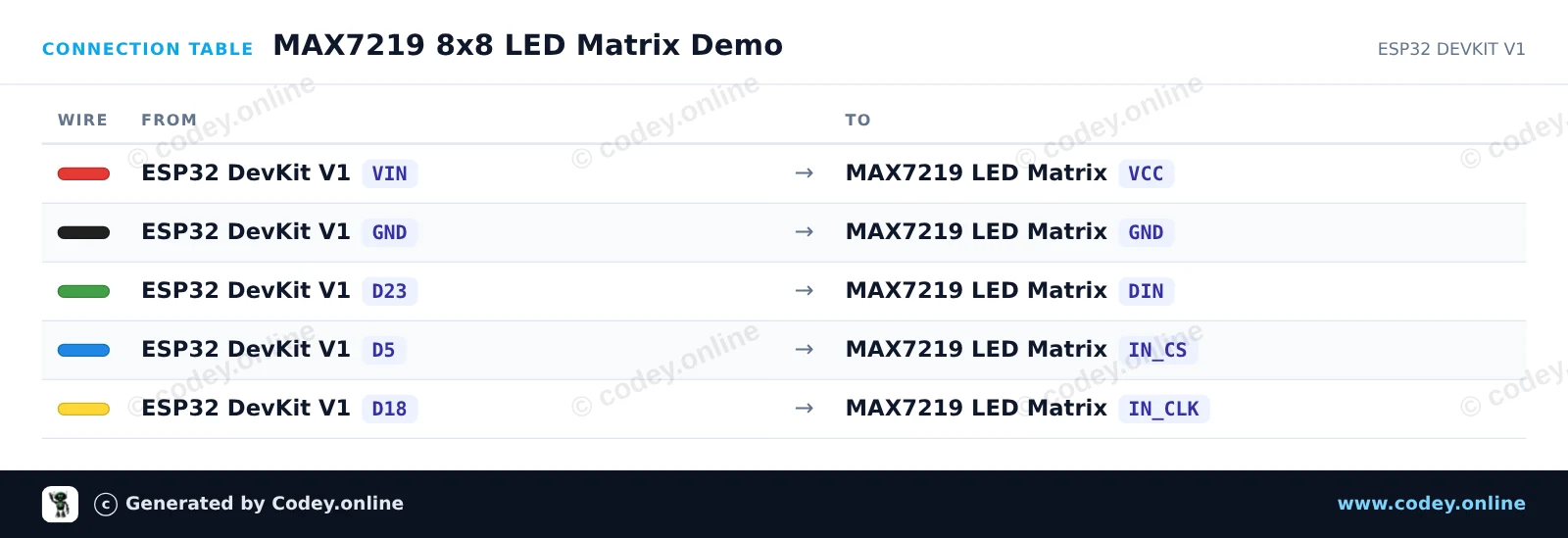
Dette projekt bruger ESP32's hardware-SPI-interface til at styre en 8x8 MAX7219 LED-matrix uden behov for eksterne biblioteker. Sketchen initialiserer displayet og skifter mellem at vise et smiley-ansigt, et hjerteikon og en række-scan-animation.
/*
 * ==================================================================
 *  Generated by Codey.online  —  https://www.codey.online
 * ==================================================================
 *  Project   : MAX7219 8x8 LED Matrix Demo
 *  Board     : ESP32 DEVKIT V1 (esp32:esp32:esp32doit-devkit-v1)
 *  Parts     : LED Matrix Module MAX7219
 *  Libraries : none (built-in)
 *
 *  Codey Online is an AI-powered browser IDE for Arduino and ESP32.
 *  Describe your project and Codey writes the code, draws the wiring
 *  diagram and uploads it to your board, straight from the browser.
 *  This code is free to use, modify and share, without warranty.
 * ==================================================================
 */

#include <SPI.h>

const int CS_PIN = 5;

// MAX7219 register addresses
const byte REG_NOOP   = 0x00;
const byte REG_DIGIT0 = 0x01;
const byte REG_DECODE = 0x09;
const byte REG_INTEN  = 0x0A;
const byte REG_SCAN   = 0x0B;
const byte REG_SHUT   = 0x0C;
const byte REG_TEST   = 0x0F;

// 8x8 Bitmaps
const byte SMILE[8] = {
  0b00111100,
  0b01000010,
  0b10100101,
  0b10000001,
  0b10100101,
  0b10011001,
  0b01000010,
  0b00111100
};

const byte HEART[8] = {
  0b00000000,
  0b01100110,
  0b11111111,
  0b11111111,
  0b11111111,
  0b01111110,
  0b00111100,
  0b00011000
};

void max7219Send(byte reg, byte data) {
  digitalWrite(CS_PIN, LOW);
  SPI.transfer(reg);
  SPI.transfer(data);
  digitalWrite(CS_PIN, HIGH);
}

void clearDisplay() {
  for (byte i = 1; i <= 8; i++) {
    max7219Send(i, 0x00);
  }
}

void displayBitmap(const byte bitmap[8]) {
  for (byte i = 0; i < 8; i++) {
    max7219Send(i + 1, bitmap[i]);
  }
}

void setup() {
  Serial.begin(115200);
  pinMode(CS_PIN, OUTPUT);
  digitalWrite(CS_PIN, HIGH);

  // Initialize hardware SPI (SCK=18, MISO=19, MOSI=23, SS=5)
  SPI.begin(18, 19, 23, CS_PIN);

  // Configure MAX7219 registers
  max7219Send(REG_TEST, 0x00);   // Normal operation (display test off)
  max7219Send(REG_SCAN, 0x07);   // Scan all 8 digits/rows
  max7219Send(REG_DECODE, 0x00); // Raw matrix mode (no BCD decoding)
  max7219Send(REG_INTEN, 0x04);  // Medium brightness (0x00 to 0x0F)
  max7219Send(REG_SHUT, 0x01);   // Normal operation (wake up)
  clearDisplay();

  Serial.println("MAX7219 LED Matrix ready!");
}

void loop() {
  // Show Smiley Face
  displayBitmap(SMILE);
  delay(2000);

  // Show Heart Icon
  displayBitmap(HEART);
  delay(2000);

  // Row scan animation
  clearDisplay();
  for (byte r = 1; r <= 8; r++) {
    max7219Send(r, 0xFF);
    delay(100);
    max7219Send(r, 0x00);
  }
}Wiring diagram and example code generated by Codey.online — https://www.codey.online





 English
  Nederlands
  Frans
Frans  Deutsch
  Italiano
  Español
  Suomi
Suomi  Polski
  Ελληνικά
  Български
  Čeština
  Hrvatski
  Svenska
  Aileen