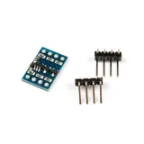
SKU: ot8520 Varenummer: NA018 EAN: 8720828223239

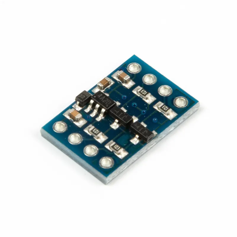
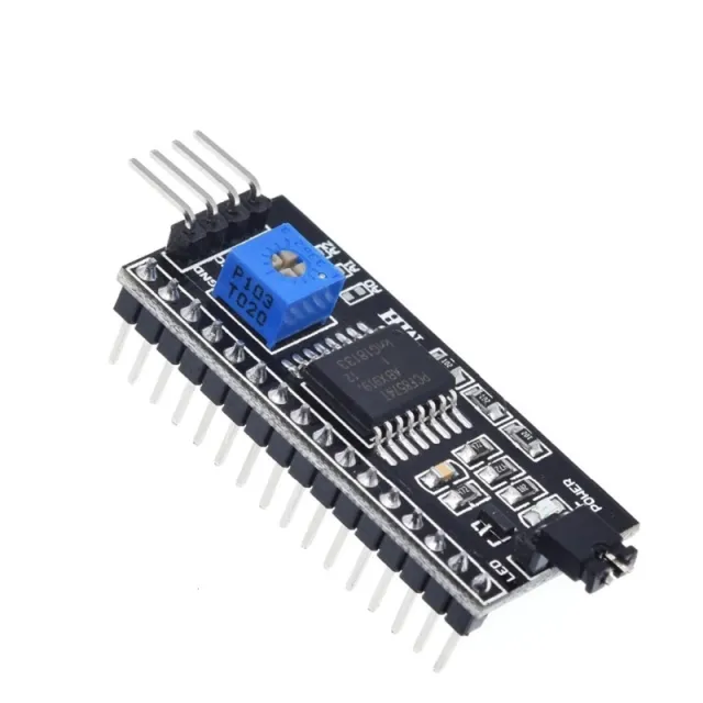
Nogle moduler arbejder med 3.3V I2C eller UART, så kan dette modul omdanne spændingen, hvis dit system arbejder med 5V.(f.eks. din 5V Arduino)
Derudover er der indbygget en spændingsregulator, som omdanner 5V til 3.3V op til 100mA, også praktisk hvis du skal forsyne et modul med 3.3V, som ikke har en indbygget spændingsregulator.
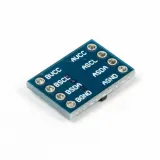
Benene er angivet på undersiden:
AVCC tilsluttes 5V
ASCL tilsluttes SCL/TX-pin på 5V-system
ASDA tilsluttes SDA/RX-pin på 5V-system
AGND tilsluttes GND på 5V-system
BVCC tilsluttes 3.3V fra systemet
BSCL tilsluttes SCL/RX-pin på 3.3V-system
BSDA tilsluttes SDA/TX-pin på 3.3V-system
BGND tilsluttes GND på 3.3V-system
Dette modul er i princippet kun egnet til at gå fra 5V til 3.3V. Spændingsregulatoren kan nemlig kun omdanne 5V til 3.3V.
Hvis dit system er 3.3V, og du vil tilslutte et 5V-modul, skal du tilslutte det som følger:
AVCC tilsluttes 5V (5V-forsyningslinje)
ASCL tilsluttes SCL/TX-pin på 5V-system
ASDA tilsluttes SDA/RX-pin på 5V-system
AGND tilsluttes GND på 5V-system
BVCC ikke tilsluttes
BSCL tilsluttes SCL/RX-pin på 3.3V-system
BSDA tilsluttes SDA/TX-pin på 3.3V-system
BGND tilsluttes GND på 3.3V-system
Bemærk: Pin headers til dette modul er endnu ikke loddet. Hvis du vil bruge headers, skal de loddes selv.
Sådan tilslutter du I2C-UART Bi-Direktionel Logic Level Converter 5V-3.3V 2-kanals til en Arduino UNO eller ESP32, med en eksempelsketch, du kan uploade med det samme.
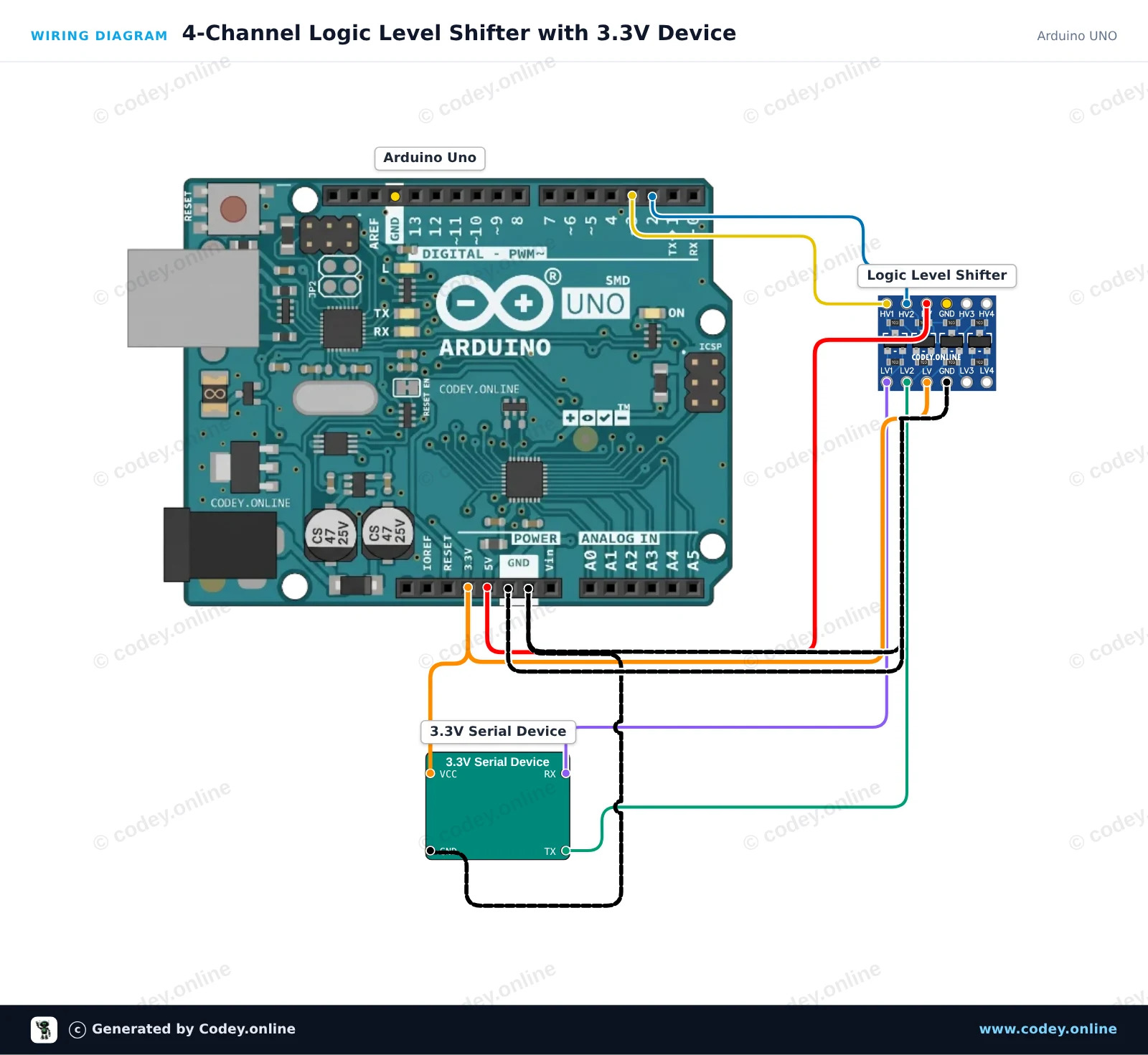
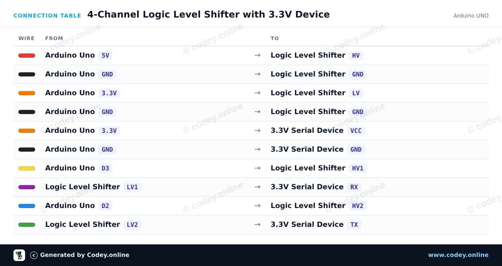
Dette kredsløb forbinder sikkert 5V Arduino Uno til en 3.3V seriel enhed ved hjælp af den 4-kanals tovejskompatible logikniveau-omformer. Arduino sender og modtager seriedata via software serial (pins 2 and 3), mens niveauomformeren oversætter signaler mellem 5V (HV) og 3.3V (LV). Åbn Serial Monitor ved 115200 baud for at overvåge kommunikationen.
/*
 * ==================================================================
 *  Generated by Codey.online  —  https://www.codey.online
 * ==================================================================
 *  Project   : 4-Channel Logic Level Shifter with 3.3V Device
 *  Board     : Arduino UNO (arduino:avr:uno)
 *  Parts     : Logic Level Shifter 4-channel
 *  Libraries : none (built-in)
 *
 *  Codey Online is an AI-powered browser IDE for Arduino and ESP32.
 *  Describe your project and Codey writes the code, draws the wiring
 *  diagram and uploads it to your board, straight from the browser.
 *  This code is free to use, modify and share, without warranty.
 * ==================================================================
 */

#include <SoftwareSerial.h>

// Arduino Uno pins connected to the HV (5V) side of the level shifter
const int rxPin = 2; // HV2 (receives translated 5V from 3.3V device TX)
const int txPin = 3; // HV1 (transmits 5V to be translated to 3.3V device RX)

SoftwareSerial deviceSerial(rxPin, txPin);

void setup() {
  Serial.begin(115200);
  deviceSerial.begin(9600);

  Serial.println(F("Logic Level Shifter Demo Initialized."));
  Serial.println(F("Forwarding serial data between USB and 3.3V device..."));
}

void loop() {
  // Forward data from USB Serial to 3.3V device
  if (Serial.available()) {
    char c = Serial.read();
    deviceSerial.write(c);
  }

  // Forward data from 3.3V device to USB Serial
  if (deviceSerial.available()) {
    char c = deviceSerial.read();
    Serial.write(c);
  }
}Wiring diagram and example code generated by Codey.online — https://www.codey.online
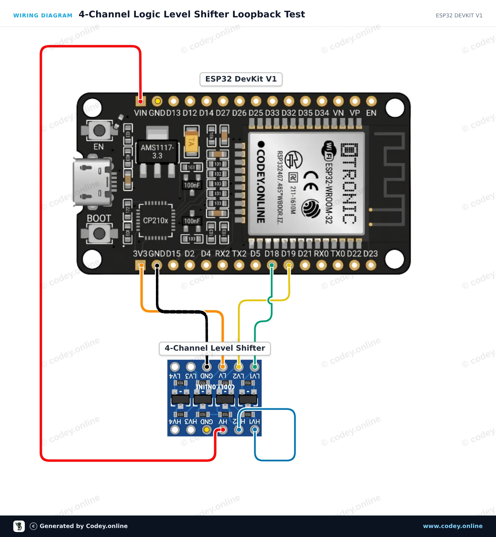
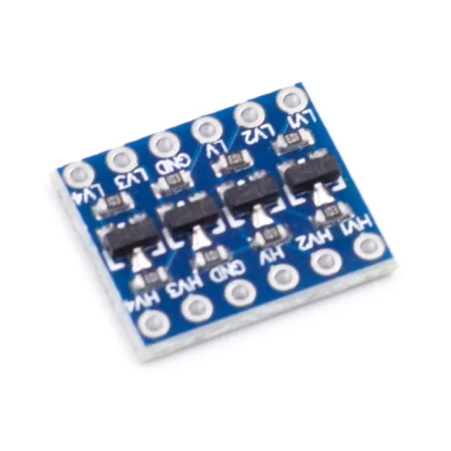
Dette projekt демонстрerer tovejs spændingstranslation med 4-kanals logic level shifter. ESP32 sender et 3.3V-signal til LV1, som hæves til 5V på HV1. En jumper forbinder HV1 til HV2 og sænker 5V-signalet tilbage til 3.3V på LV2, så det kan verificeres af ESP32.
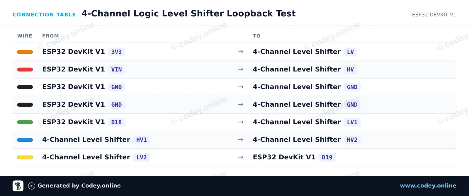
/*
 * ==================================================================
 *  Generated by Codey.online  —  https://www.codey.online
 * ==================================================================
 *  Project   : 4-Channel Logic Level Shifter Loopback Test
 *  Board     : ESP32 DEVKIT V1 (esp32:esp32:esp32doit-devkit-v1)
 *  Parts     : Logic Level Shifter 4-channel
 *  Libraries : none (built-in)
 *
 *  Codey Online is an AI-powered browser IDE for Arduino and ESP32.
 *  Describe your project and Codey writes the code, draws the wiring
 *  diagram and uploads it to your board, straight from the browser.
 *  This code is free to use, modify and share, without warranty.
 * ==================================================================
 */

// 4-Channel Logic Level Shifter Loopback Demo
// Sends 3.3V pulses on GPIO 18 (LV1), stepped up to 5V (HV1),
// looped to HV2 (5V), and stepped down to 3.3V on LV2 to read on GPIO 19.

const int TX_PIN = 18; // 3.3V Output to LV1
const int RX_PIN = 19; // 3.3V Input from LV2

void setup() {
  Serial.begin(115200);
  while (!Serial) {
    delay(10);
  }

  pinMode(TX_PIN, OUTPUT);
  pinMode(RX_PIN, INPUT);

  Serial.println("=== Logic Level Shifter Loopback Test ===");
}

void loop() {
  // Test HIGH state
  digitalWrite(TX_PIN, HIGH);
  delay(10);
  int highRead = digitalRead(RX_PIN);

  // Test LOW state
  digitalWrite(TX_PIN, LOW);
  delay(10);
  int lowRead = digitalRead(RX_PIN);

  // Report status
  Serial.print("Sent HIGH -> Read: ");
  Serial.print(highRead == HIGH ? "HIGH [PASS]" : "LOW  [FAIL]");
  Serial.print(" | Sent LOW -> Read: ");
  Serial.println(lowRead == LOW ? "LOW  [PASS]" : "HIGH [FAIL]");

  delay(1000);
}Wiring diagram and example code generated by Codey.online — https://www.codey.online





 English
  Nederlands
  Frans
Frans  Deutsch
  Italiano
  Español
  Suomi
Suomi  Polski
  Ελληνικά
  Български
  Čeština
  Hrvatski
  Aileen