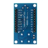
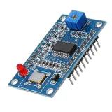
SKU: OT3459 Varenummer: NA416 EAN: 8720618690838

Signalgeneratorer/funktionsgeneratorer er superpraktiske fra RF til embedded logik, men de er som regel ikke super billige.
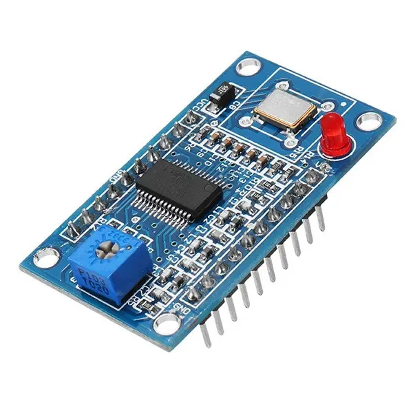
Gode nyheder: med dette AD9850 DDS Modul kan du med lidt montering lave din egen fleksible, funktionelle og brugervenlige Arduino frekvensgenerator!
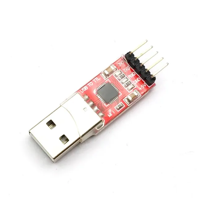
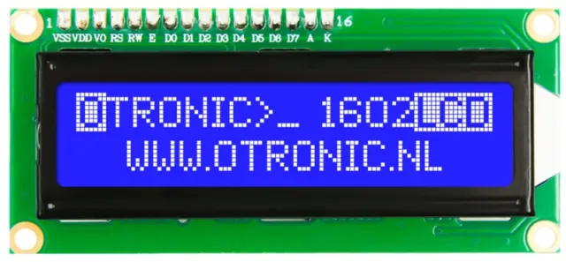
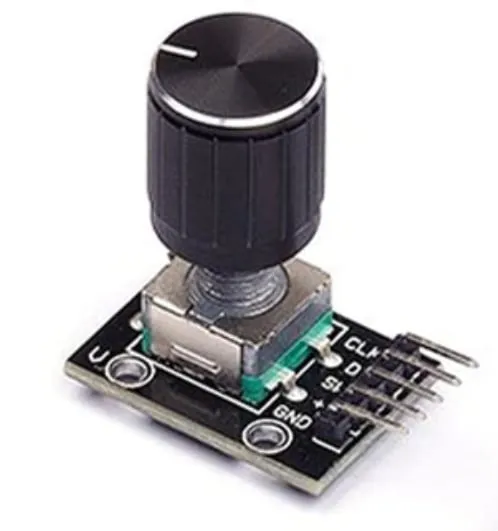
Med et LED display, rotary Potentiometer, og en Arduino kan du lave en let anvendelig, fritstående signalgenerator. (Glem ikke at anskaffe en CP2102 USb til TTL Serial Converter, hvis du ikke allerede har en)
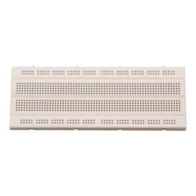
Du kan også vælge kun at kombinere den med Arduino Uno på et breadboard.
En helt anden vej er at bruge dette modul til at lave din egen Software Defined Radio (SDR).
Kort sagt, et flot modul at komme i gang med!
Egenskaber:
ANVENDELSER:
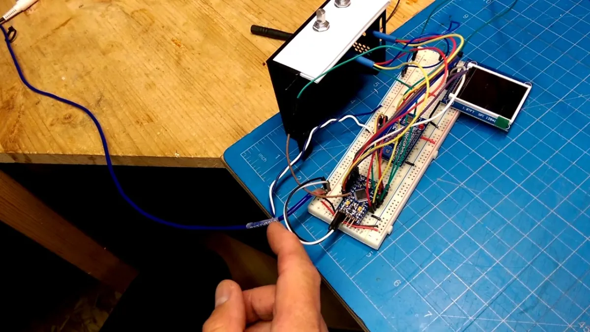
Ved afspilning indlæses videoen fra YouTube.
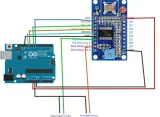
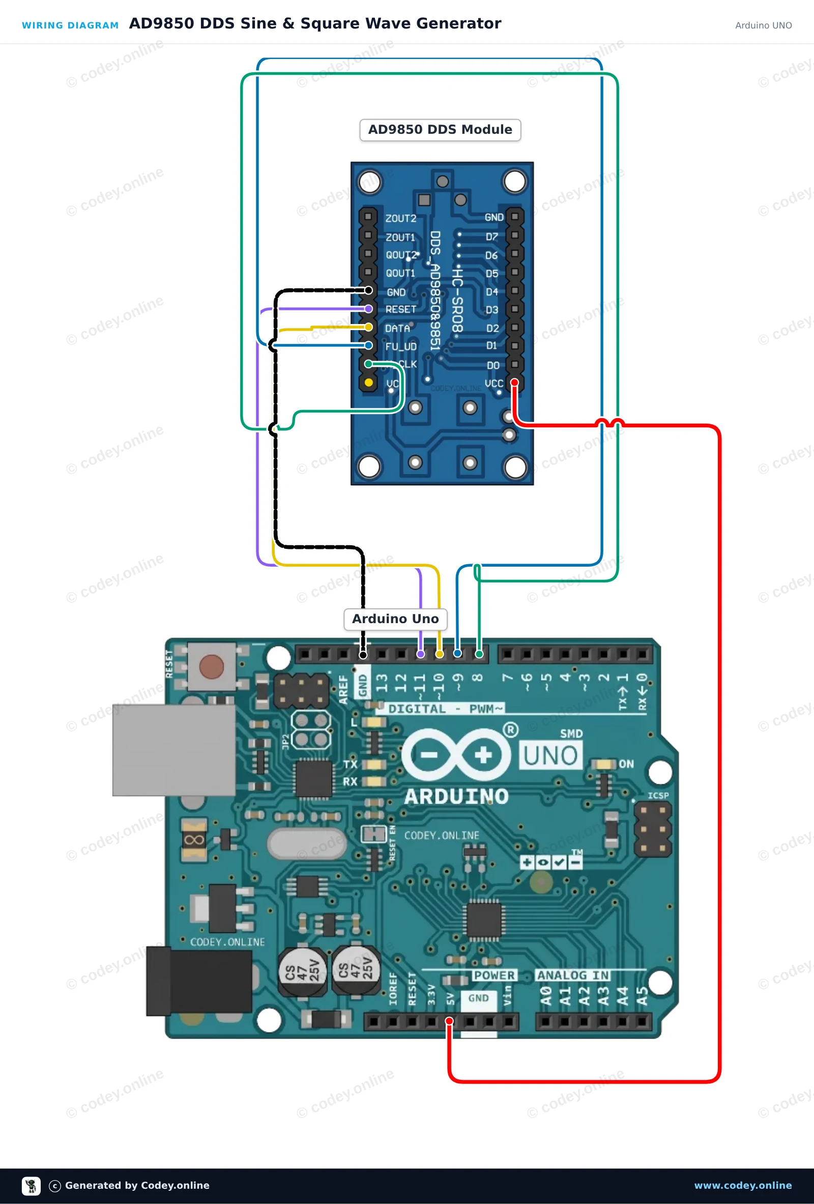
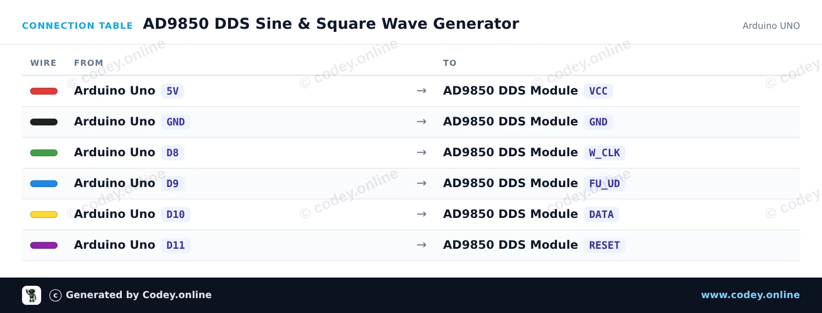
Sådan tilslutter du AD9850 DDS Signalgenerator Modul til en Arduino UNO eller ESP32, med en eksempelsketch, du kan uploade med det samme.
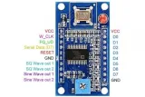
Dette projekt styrer et AD9850 DDS-modul via en 4-tråds seriel grænseflade for at generere præcise sinus- og firkantfrekvenser. Arduino initialiserer DDS-modulet og skifter periodisk udgangsfrekvensen mellem 1 kHz, 10 kHz og 100 kHz. Tilslut et oscilloskop eller en frekvenstæller til ZOUT1 (sinusbølge) eller QOUT1 (firkantbølge) for at inspicere udgangssignalet.
/*
 * ==================================================================
 *  Generated by Codey.online  —  https://www.codey.online
 * ==================================================================
 *  Project   : AD9850 DDS Sine & Square Wave Generator
 *  Board     : Arduino UNO (arduino:avr:uno)
 *  Parts     : AD9850 DDS Signal Generator Module
 *  Libraries : none (built-in)
 *
 *  Codey Online is an AI-powered browser IDE for Arduino and ESP32.
 *  Describe your project and Codey writes the code, draws the wiring
 *  diagram and uploads it to your board, straight from the browser.
 *  This code is free to use, modify and share, without warranty.
 * ==================================================================
 */

const int PIN_W_CLK = 8;
const int PIN_FQ_UD = 9;   // Labeled FU_UD on module
const int PIN_DATA  = 10;
const int PIN_RESET = 11;

const unsigned long AD9850_REF_CLOCK = 125000000UL; // 125 MHz reference oscillator

void pulsePin(int pin) {
  digitalWrite(pin, HIGH);
  delayMicroseconds(1);
  digitalWrite(pin, LOW);
  delayMicroseconds(1);
}

void ad9850Reset() {
  digitalWrite(PIN_RESET, HIGH);
  delayMicroseconds(1);
  digitalWrite(PIN_RESET, LOW);
  delayMicroseconds(1);
  pulsePin(PIN_W_CLK);
  pulsePin(PIN_FQ_UD);
}

void ad9850SetFrequency(double freqHz) {
  // Calculate 32-bit tuning word: (freq * 2^32) / ReferenceClock
  uint32_t tuningWord = (uint32_t)((freqHz * 4294967296.0) / (double)AD9850_REF_CLOCK);

  // Transmit 32-bit frequency tuning word (LSB first)
  for (int i = 0; i < 32; i++) {
    digitalWrite(PIN_DATA, (tuningWord >> i) & 0x01);
    pulsePin(PIN_W_CLK);
  }

  // Transmit 8 control/phase bits (all 0 for normal operation)
  for (int i = 0; i < 8; i++) {
    digitalWrite(PIN_DATA, LOW);
    pulsePin(PIN_W_CLK);
  }

  // Latch the updated frequency into the DDS core
  pulsePin(PIN_FQ_UD);
}

void setup() {
  pinMode(PIN_W_CLK, OUTPUT);
  pinMode(PIN_FQ_UD, OUTPUT);
  pinMode(PIN_DATA, OUTPUT);
  pinMode(PIN_RESET, OUTPUT);

  digitalWrite(PIN_W_CLK, LOW);
  digitalWrite(PIN_FQ_UD, LOW);
  digitalWrite(PIN_DATA, LOW);
  digitalWrite(PIN_RESET, LOW);

  Serial.begin(115200);
  while (!Serial) {
    ;
  }

  Serial.println(F("AD9850 DDS Generator Initialized"));
  ad9850Reset();
}

void loop() {
  const double testFrequencies[] = {1000.0, 10000.0, 100000.0};

  for (int i = 0; i < 3; i++) {
    double freq = testFrequencies[i];
    ad9850SetFrequency(freq);
    Serial.print(F("Output frequency set to: "));
    Serial.print(freq);
    Serial.println(F(" Hz"));
    delay(3000);
  }
}Wiring diagram and example code generated by Codey.online — https://www.codey.online
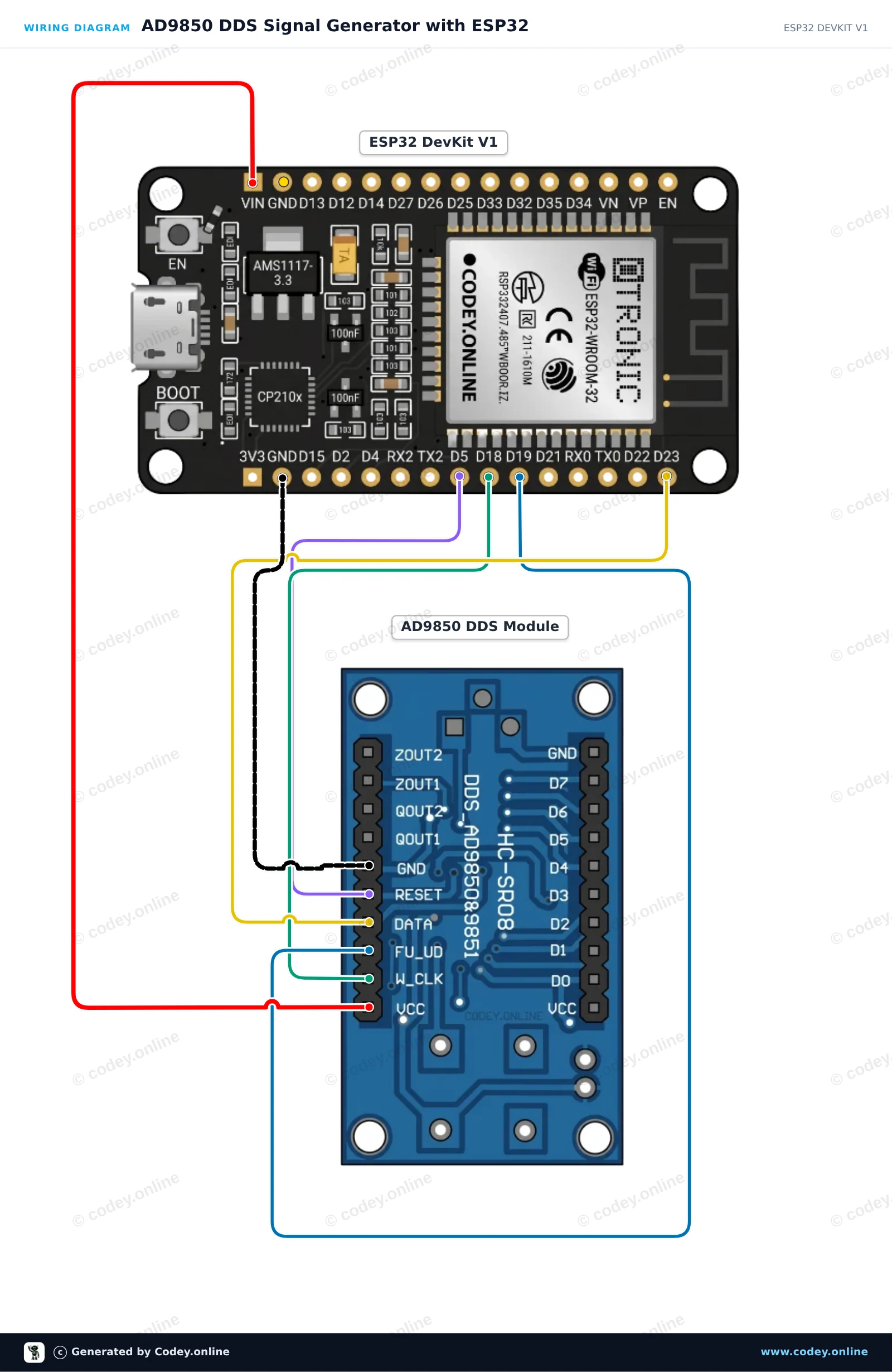
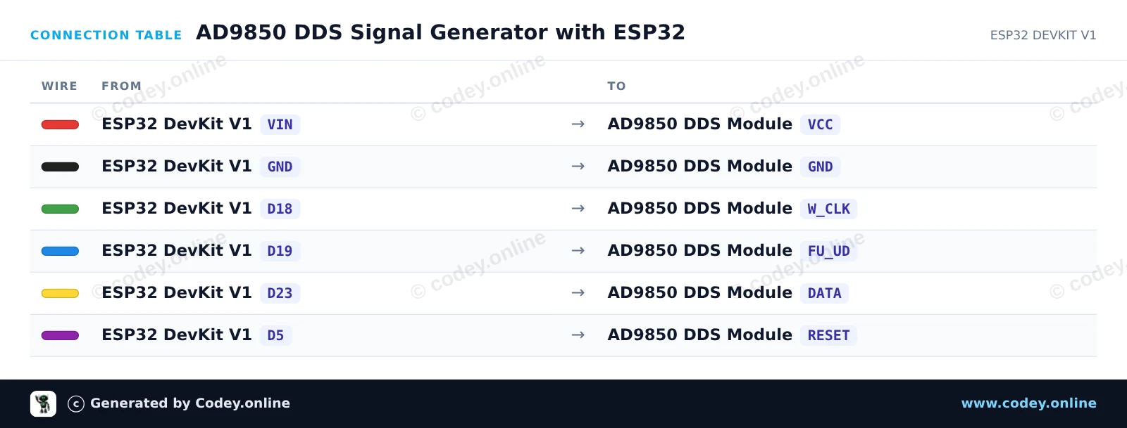
Dette projekt genererer præcise sinus- og firkantsignaler ved hjælp af AD9850 DDS-modulet styret af en ESP32. Sketchen gennemgår en sekvens af frekvenser (1 kHz, 10 kHz, 100 kHz og 1 MHz) hvert 3 seconds. Tilslut et oscilloskop eller en frekvenstæller til ZOUT1 for et sinussignal eller til QOUT1 for et firkantet output.
/*
 * ==================================================================
 *  Generated by Codey.online  —  https://www.codey.online
 * ==================================================================
 *  Project   : AD9850 DDS Signal Generator with ESP32
 *  Board     : ESP32 DEVKIT V1 (esp32:esp32:esp32doit-devkit-v1)
 *  Parts     : AD9850 DDS Signal Generator Module
 *  Libraries : none (built-in)
 *
 *  Codey Online is an AI-powered browser IDE for Arduino and ESP32.
 *  Describe your project and Codey writes the code, draws the wiring
 *  diagram and uploads it to your board, straight from the browser.
 *  This code is free to use, modify and share, without warranty.
 * ==================================================================
 */

// AD9850 DDS Signal Generator Demo on ESP32
const int W_CLK_PIN = 18;
const int FU_UD_PIN = 19;
const int DATA_PIN  = 23;
const int RESET_PIN = 5;

// 125 MHz reference clock crystal on board
const double REF_CLK = 125000000.0;

const double testFrequencies[] = {1000.0, 10000.0, 100000.0, 1000000.0};
const int numFrequencies = sizeof(testFrequencies) / sizeof(testFrequencies[0]);
int currentFreqIndex = 0;

void pulseHigh(int pin) {
  digitalWrite(pin, HIGH);
  delayMicroseconds(1);
  digitalWrite(pin, LOW);
  delayMicroseconds(1);
}

void resetAD9850() {
  pulseHigh(RESET_PIN);
  pulseHigh(W_CLK_PIN);
  pulseHigh(FU_UD_PIN); // Enable serial load mode
}

void sendFrequency(double frequency) {
  uint32_t tuningWord = (uint32_t)((frequency * 4294967296.0) / REF_CLK);

  // Send 32-bit frequency tuning word (LSB first)
  for (int i = 0; i < 32; i++) {
    digitalWrite(DATA_PIN, (tuningWord >> i) & 0x01);
    pulseHigh(W_CLK_PIN);
  }

  // Send 8 control/phase bits (0x00 for 0 phase offset)
  for (int i = 0; i < 8; i++) {
    digitalWrite(DATA_PIN, LOW);
    pulseHigh(W_CLK_PIN);
  }

  // Latch new frequency to output
  pulseHigh(FU_UD_PIN);
}

void setup() {
  Serial.begin(115200);
  delay(500);
  Serial.println("AD9850 DDS Signal Generator Initializing...");

  pinMode(W_CLK_PIN, OUTPUT);
  pinMode(FU_UD_PIN, OUTPUT);
  pinMode(DATA_PIN,  OUTPUT);
  pinMode(RESET_PIN, OUTPUT);

  digitalWrite(W_CLK_PIN, LOW);
  digitalWrite(FU_UD_PIN, LOW);
  digitalWrite(DATA_PIN,  LOW);
  digitalWrite(RESET_PIN, LOW);

  resetAD9850();
  Serial.println("AD9850 ready!");
}

void loop() {
  double freq = testFrequencies[currentFreqIndex];
  sendFrequency(freq);

  Serial.print("Output frequency set to: ");
  Serial.print(freq, 0);
  Serial.println(" Hz");

  currentFreqIndex = (currentFreqIndex + 1) % numFrequencies;
  delay(3000);
}Wiring diagram and example code generated by Codey.online — https://www.codey.online





 English
  Nederlands
  Frans
Frans  Deutsch
  Italiano
  Español
  Suomi
Suomi  Polski
  Ελληνικά
  Български
  Čeština
  Hrvatski
  Aileen